I am planning a project that will involve up to 30 pumps working together to move 1,375 gallons of Spirulina culture in a little over 15 minutes. The reason for using so many is that it just happens to be the cheapest option available that is appropriately sized for my area and is self-priming and satisfies my food grade requirements. There are a few details I am not entirely sure how best to approach, but will provide all the details in case something is important that I don't realize.
Each pump is rated at 3 GPM. Max inlet Pressure 30 PSI. Self priming up to 9.0 Ft Vertical Max.
Auto Shut Off: 45 PSI; Auto Turn on: 25 PSI
Pumps use 1/2 inch PVC.
Planning to use anti-backflow in the outflow followed by clear PVC so I can visually inspect to make sure all the pumps are working properly at any given time.
30 pumps is the maximum, but I may have to add 10 pumps at a time, so it will likely begin with 10, then increase to 20, then increase to 30.
The surface of the culture is 3 feet below the floor of the harvesting room, and it simply needs to go up an extra 3 feet minimum to then gravity feed through the harvesting apparatus, so in a perfect world it would only be a 6 foot head.
The harvesting apparatus can hold at most 100 gallons of culture. The drain on the bottom is a 6" pipe that runs down below the frost line then hits a 90 degree elbow (still 6") then vertically runs 9 feet before reaching another 90 degree elbow downward which then immediately connects to a unit I built that drops to 4 inches then immediately after 2 inches before going through a 90 degree 2 inch elbow. I can confirm that this does not leak, despite the increase in pressure here. This 2 inch pipe then connects to a series of control valves that allow me to choose which tank to drain back into, or into a storm drain for when I need to clean the line out to not go back in.
Each foot of water in the tank is estimated to be approximately 90 cubic feet, 673.25 gallons.
Now, here are the problems:
1.) The drain size cannot be increased, and it should never fill up with water unless a plug is inserted. As such, I need to be sure that 90 gallons per minute dropping down by gravity will drain just fine here - even if pressure increases. If there would be a problem with that I will have to reduce the maximum pumps in the system accordingly.
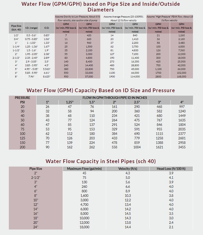
2.) I can only fit 10 pumps per 5 foot wide shelf, meaning I will need to use 3 shelves, so each shelf would have 10 half inch pipes. I want to preserve the 30 GPM without increasing the pressure high enough to trigger the auto shut off. For each such shelf I'd like to use a 2" pipe. Would this be too small? If so, how large does it need to be?
3.) Where the 3 pipes from the 3 shelves connect, can they connect to the same size pipe? For example, if I went from 1/2 inch to 2" can I use a cross pipe with maybe an anti-backflow on each of the initial 3 leading into the 4th?
4.) When it reaches the end, I want to reduce the pressure that falls directly onto the harvesting apparatus as much as possible without reducing the flow rate. If I used a T at the end to feet into a 3 foot long pipe section, with a series of holes drilled into the bottom, what size would the holes need to be to flow out evenly?
5.) I have two options regarding pump placement:
a.) The best placement for wiring and heat dissipation would be on the bottom. So the bottom 10 would be on floor, and the 10 above them would be one foot higher, and the 10 above them would be one foot higher. If I went this route, the pipes would all have to flow upward without flowing back on the pipes. Would this work though, with the pipe sizes increasing before going down?
b.) I could place the pumps near the ceiling, which could also be useful since I plan on having control valves on the wall. These control valves will allow me to switch which tank is being drawn from. In this setup, the 1/2 inch pipes would flow up along the wall through the control valves and then would reach the first 10 at approximately 3.5 feet above the floor (or 6.5 foot head), the second 10 at 4.5 feet above the floor (or 7.5 feet head), and the third at 5.5 feet above the floor (or 8.5 feet head). With a max self priming head of 9 feet, I have to make sure that the water in all of the pipes and in the basin (if it is filled for washing) does not exceed 300 gallons at this height, since the head will increase as culture is pulled out. In this setup, on the outflow end, the 1/2 inch goes downward before going to a larger pipe size, and then the 3 larger pipes for each shelf will likewise all go down before connecting with the horizontal pipe connecting to the drain. The basic idea here is that if I don't have enough pumps running for full pressure to lift the culture upward through a larger than 1/2 pipe it would still work, since the larger pipes never go higher than 1/2 outflow line level.
6.) Since evaporation may occur, I was planning on using a float valve to turn a valve allowing fresh reverse osmosis water in below a given level, but I don't want the water turning on just before culture is tied up in the pipes. I figure I would just calculate the volume of all pipes and adjust the height accordingly, but does anyone know of such an item that is sensitive enough to accurately turn a pipe on when the water level falls below an exact line, and is also suitable for potable water applications?
...
Now, the reason why I can't simply use 30 1/2 pipes each with their own drain? Well, I could do that, but I am planning to have a single control valve. When the valve is opened pressure drops and the pumps turn on automatically. When the valve is closed the pressure increases and all pumps turn off automatically. There would also be a master off switch just in case though.
This is all being done as part of a home based business, and I am learning as I go. Since each component is so expensive I can't afford to make mistakes with this next phase.
I would appreciate any help on any of these items that can be provided, especially for the simplest part of the problems: Sizing the pipes appropriately, and placing them properly.
Each pump is rated at 3 GPM. Max inlet Pressure 30 PSI. Self priming up to 9.0 Ft Vertical Max.
Auto Shut Off: 45 PSI; Auto Turn on: 25 PSI
Pumps use 1/2 inch PVC.
Planning to use anti-backflow in the outflow followed by clear PVC so I can visually inspect to make sure all the pumps are working properly at any given time.
30 pumps is the maximum, but I may have to add 10 pumps at a time, so it will likely begin with 10, then increase to 20, then increase to 30.
The surface of the culture is 3 feet below the floor of the harvesting room, and it simply needs to go up an extra 3 feet minimum to then gravity feed through the harvesting apparatus, so in a perfect world it would only be a 6 foot head.
The harvesting apparatus can hold at most 100 gallons of culture. The drain on the bottom is a 6" pipe that runs down below the frost line then hits a 90 degree elbow (still 6") then vertically runs 9 feet before reaching another 90 degree elbow downward which then immediately connects to a unit I built that drops to 4 inches then immediately after 2 inches before going through a 90 degree 2 inch elbow. I can confirm that this does not leak, despite the increase in pressure here. This 2 inch pipe then connects to a series of control valves that allow me to choose which tank to drain back into, or into a storm drain for when I need to clean the line out to not go back in.
Each foot of water in the tank is estimated to be approximately 90 cubic feet, 673.25 gallons.
Now, here are the problems:
1.) The drain size cannot be increased, and it should never fill up with water unless a plug is inserted. As such, I need to be sure that 90 gallons per minute dropping down by gravity will drain just fine here - even if pressure increases. If there would be a problem with that I will have to reduce the maximum pumps in the system accordingly.
2.) I can only fit 10 pumps per 5 foot wide shelf, meaning I will need to use 3 shelves, so each shelf would have 10 half inch pipes. I want to preserve the 30 GPM without increasing the pressure high enough to trigger the auto shut off. For each such shelf I'd like to use a 2" pipe. Would this be too small? If so, how large does it need to be?
3.) Where the 3 pipes from the 3 shelves connect, can they connect to the same size pipe? For example, if I went from 1/2 inch to 2" can I use a cross pipe with maybe an anti-backflow on each of the initial 3 leading into the 4th?
4.) When it reaches the end, I want to reduce the pressure that falls directly onto the harvesting apparatus as much as possible without reducing the flow rate. If I used a T at the end to feet into a 3 foot long pipe section, with a series of holes drilled into the bottom, what size would the holes need to be to flow out evenly?
5.) I have two options regarding pump placement:
a.) The best placement for wiring and heat dissipation would be on the bottom. So the bottom 10 would be on floor, and the 10 above them would be one foot higher, and the 10 above them would be one foot higher. If I went this route, the pipes would all have to flow upward without flowing back on the pipes. Would this work though, with the pipe sizes increasing before going down?
b.) I could place the pumps near the ceiling, which could also be useful since I plan on having control valves on the wall. These control valves will allow me to switch which tank is being drawn from. In this setup, the 1/2 inch pipes would flow up along the wall through the control valves and then would reach the first 10 at approximately 3.5 feet above the floor (or 6.5 foot head), the second 10 at 4.5 feet above the floor (or 7.5 feet head), and the third at 5.5 feet above the floor (or 8.5 feet head). With a max self priming head of 9 feet, I have to make sure that the water in all of the pipes and in the basin (if it is filled for washing) does not exceed 300 gallons at this height, since the head will increase as culture is pulled out. In this setup, on the outflow end, the 1/2 inch goes downward before going to a larger pipe size, and then the 3 larger pipes for each shelf will likewise all go down before connecting with the horizontal pipe connecting to the drain. The basic idea here is that if I don't have enough pumps running for full pressure to lift the culture upward through a larger than 1/2 pipe it would still work, since the larger pipes never go higher than 1/2 outflow line level.
6.) Since evaporation may occur, I was planning on using a float valve to turn a valve allowing fresh reverse osmosis water in below a given level, but I don't want the water turning on just before culture is tied up in the pipes. I figure I would just calculate the volume of all pipes and adjust the height accordingly, but does anyone know of such an item that is sensitive enough to accurately turn a pipe on when the water level falls below an exact line, and is also suitable for potable water applications?
...
Now, the reason why I can't simply use 30 1/2 pipes each with their own drain? Well, I could do that, but I am planning to have a single control valve. When the valve is opened pressure drops and the pumps turn on automatically. When the valve is closed the pressure increases and all pumps turn off automatically. There would also be a master off switch just in case though.
This is all being done as part of a home based business, and I am learning as I go. Since each component is so expensive I can't afford to make mistakes with this next phase.
I would appreciate any help on any of these items that can be provided, especially for the simplest part of the problems: Sizing the pipes appropriately, and placing them properly.